IMPACT TEST REQUIREMENT FOR PRESSURE VESSEL
Impact tests can cause a fortune so the pressure vessel designers try to avoid it as much as possible. Determining whether a vessel needs an impact test could be pain in a neck for someone starting as a design engineer. ASME boiler and pressure vessel code has stated some criteria, if the vessel fulfills this then impact test can be exempted otherwise we should be ready to perform this expensive test. Let’s get in more depth with an example. Below are some design parameters of a vessel that needed to be checked for the impact testing.
|
MDMT in °F |
-20 |
|
Thickness in inch |
0.5 |
|
Material |
SA-516-70 |
|
Joint Eff. |
0.85 |
|
Corrosion Allowance |
0.125 |
The assessment process is divided into four steps with each having its own touchstones. Meeting the standards of only one of the steps is enough to abstain from the test. If not, then we proceed to the next step.
Step 1: UG-20 (f)
There are five clauses given in UG-20 (f) which needs to be checked for.
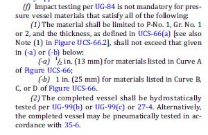
As already mentioned the material used was SA-516-70 which belongs to P-No-1 Gr-1 as given in ASME code sec IX. But to determine the thickness limitation, first we had to look into note 1, 2, 3, and 4 of UCS 66 figure to know which curve the material belonged to. We found that the material belonged to curve B.
Now according to point 1 b of UG-20(f), the maximum thickness allowed is 1 inch for curve b, c and d. So impact testing is not needed. This was the case for our project.
But let us suppose that the thickness be 1.0625” rather than 0.5”.In such case we are not exempted of the impact testing as per this section and should move to UCS 66.
Step 2: The UCS 66 figure as shown below has four curves in which MDMT is plotted as ordinate and thickness as abscissa.
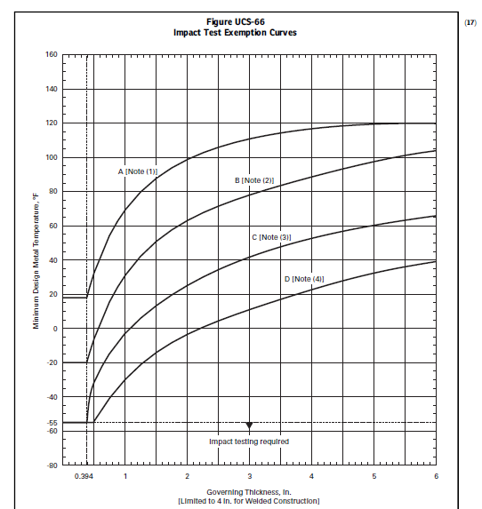
Draw a vertical line from 1.0625 thickness and similarly draw a horizontal line from -20°F MDMT. If their intersection point is below the curve B (as our material lies on this curve), we are not exempted from the impact test.
We can also check the table which represents the data of the figure shown above for impact test exemption.
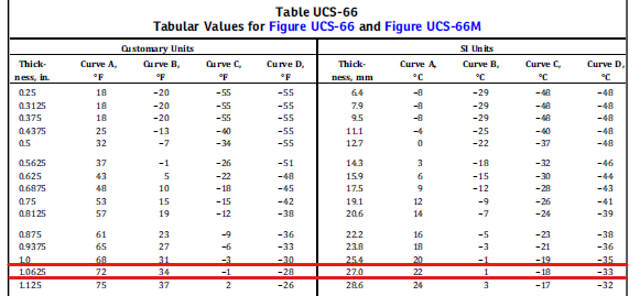
Here, it is clearly shown that our MDMT (-20°F) is below the minimum value of MDMT shown for curve B (34°F). One thing you might have noticed is that if our material was normalized, it would be in curve D and we would be exempted of impact testing in this step itself.
Step 3: UCS 66b
Now we move toward UCS 66 (b) where we calculate a ratio to determine the adjustable MDMT.
Ratio = Tr-E/tn-C
Where,
Tr is the required thickness in corroded condition.
E is the joint efficiency
tn is nominal non-corroded thickness
C is the corrosion allowance
As per our design parameters we get,
Ratio= 1*0.85/1.0625-0.125 (supposing required thickness to be 1”)
=0.90
After calculating the ratio, we know look into UCS 66 b curve. Draw a horizontal line from our ratio on the horizontal axis and mark the point that intersects the curve. From the intersection point draw a vertical line to the bottom. The temperature at which the line touches is the temperature tolerance. Here we get 10°F as an allowance on our MDMT.
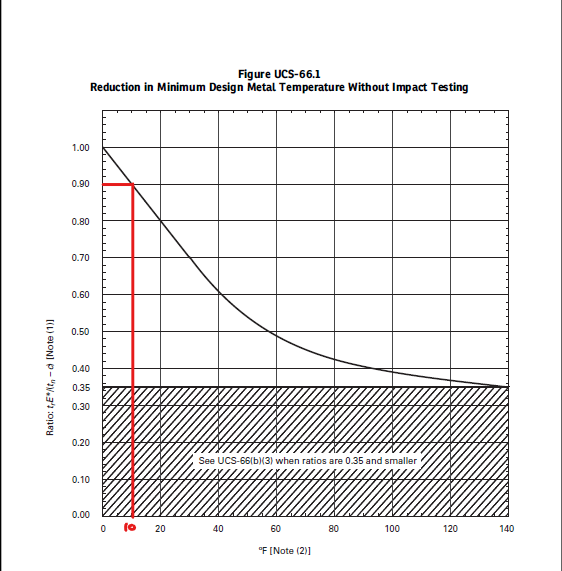
Subtracting the allowance from MDMT limit we get, 34-10=24°F. It’s still way too greater than -20°F. We are not exempted from this clause too.
Step 4: If impact test is not exempted even from UCS 66 (b) then this clause might be helpful. It says that if post weld heat treatment is carried out when it is not required, our MDMT can be reduced by 30°F. Our minimum permissible MDMT now becomes 24-30=-6°F which is still warmer than -20°F. Hence, we see that impact test will be mandatory in this case as criteria of not a single step is fulfilled.